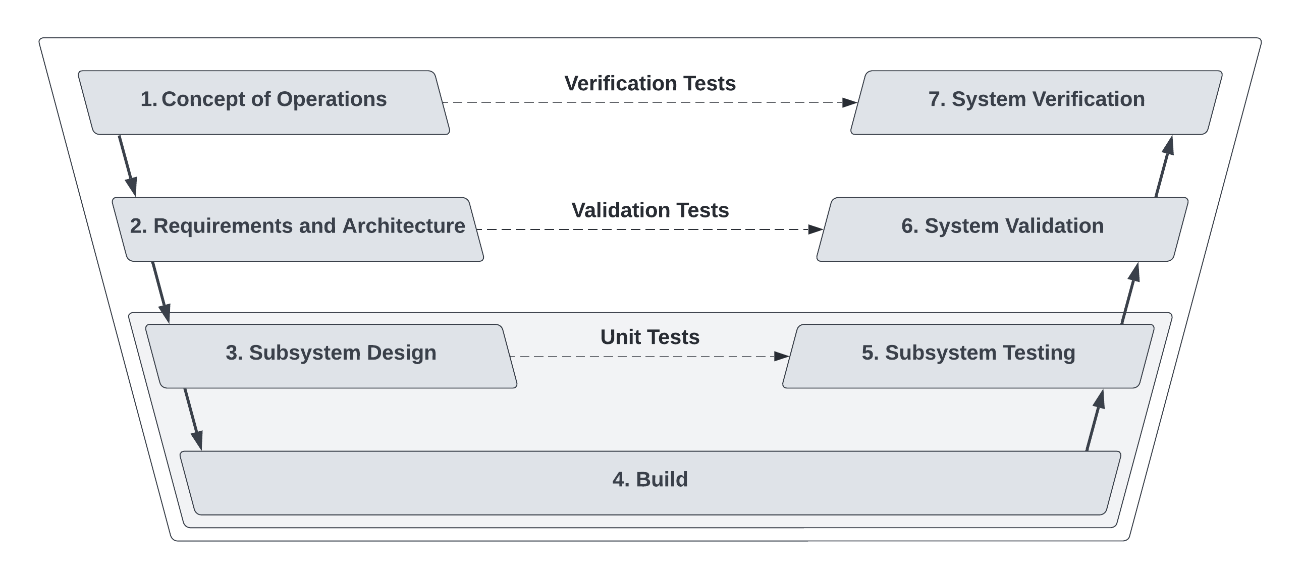
Systems Process
There are two common methods of system design process:
- Waterfall, having a rigid plan with milestones. The V-model is one example of Waterfall development.
- Agile, using Sprints as an interval of time to work on a set of tasks. Then the team reviews what was completed in the Sprint, and replans what will be worked in the next Sprint.
Waterfall is often described as an old practice that is not aligned with the quick pace of modern design projects, where requirements change over time. This is epitomized by multi-decade military projects that are sometimes obsolete before they ever get deployed in service. Though Agile is common in industry today, there are blended approaches that have an architecture planning phase at the beginning of a project, followed by design cycles with a feedback loop for replanning. Lockheed Martin's Skunk Works® has designed and build prototype planes in 2 year design cycles for the past 70 years, long before Agile was defined.
TIP
Make your design cycles as short as feasible. The typical hardware designer concern is that it is difficult to add new features to a design late in a project. The hope with a short design cycle is that you realize these deficiencies through testing, and start a new clean sheet design for the next iteration.
The rest of this page will describe the blended approach for projects including hardware and software.
Agile V-model

-
Concept of Operations (ConOps)
- What is the problem or application?
- How will the deployed system function?
- What are the nominal operating conditions?
- What are the off-nominal operating conditions, and the probablity of experiencing them in the system's service life? (edge cases)
- How will the system be shipped, deployed, operated, maintained, and retired? (full life cycle)
- Write the Verification Test Plan.
-
Requirements and Architecture
- Requirements
- Codify the ConOps into a list of binary tests.
- Try to avoid large dependency graphs for these binary requirements.
- List the industry standards that will structure the Validation Tests
- List the industry standards that will be used by designers.
- Write the Validation Test Plan.
- Architecture
- Separate the functions of the system into subsystems.
- Define inputs and outputs to these subsystems.
- Define interfaces between subsystems. (mechanical, electrical, data busses, software API)
- Requirements
-
Subsystem Design
- Review subsystem requirements and interfaces.
- Review suggested inductry standards.
- Choose components, libraries, and reference material.
- Design. (wiring diagrams, sketches, CAD, writing firmware and software)
- Writing documentation.
-
Build
- Ordering or fabricating components.
- Hardware assembly, wiring, calibrating components.
- Updating documentating.
-
Subsystem Testing
- Are the performance outputs as expected?
- Fluid leaks?
- Unachievable or expensive mechanical tolerances?
- Incorrect design details like cable pinout?
- Software state machine bugs?
-
System Validation Testing
- Perform the Validation Test Plan.
- Does the system pass all the binary tests?
- Should this system be iterated on, in hopes of passing the failed tests?
- Should we deviate from the intented performance, and disregard a failed test?
NOTE
Example: System shall be able to drive at 3 m/s. The tested system was able to drive at 2.8 m/s on flat ground. We will deviate from the intended requrement, and review again during Verification Testing. -
System Verification Testing
- Perform the Verification Test Plan.
- Does the system meet the intended use case?